|
|
|
|||||||||||||||||||||
| ALL HOLES CLOSED WILL DELIVER 60 P.P.M PER PUMP CYCLE. | |||||||||||||||||||||||
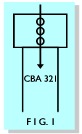 |
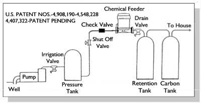
This chart is for a 42 gallon or equivalent pressure tank. When using an 80 gallon pressure tank, the P.P.M. amount will be 50% less per pump cycle. A 20 gallon pressure tank will yield 2 times the amount. Each number or letter will show a different hole in the cap. Line up the 3 holes in the cap with the proper number or letter directly under it (as per figure 1). The hole in the tube should show in the center of the hole in the cap. |
|||
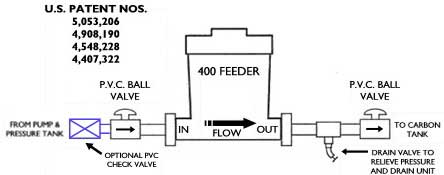
| UNITS MUST BE INSTALLED AFTER PRESSURE TANK | ||||
| Install P.V.C. check valve BEFORE the feeder if water is used after pressure tank and before feeder inlet. |
||||
 |
||||
| USE CAUTION WHEN DRAINING CHLORINE: Chlorine can bleach clothes and may burn eyes and skin. See manufacturer details for proper handling. | ||||
| When removing center tube for cleaning, check hole setting in cap. After cleaning, be sure the setting is the same before replacing the cap. | ||||
Center tube MUST BE REMOVED AND CLEANED or replaced with the extra center tube and cap each time before refilling.
|
||||
AN EXPLOSION CAN OCCUR
|
|
|
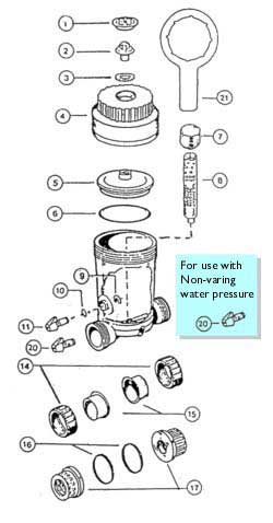
| The UNIVERSAL CHEMICAL FEEDER will operate on a varying pressure such as a home well system or on a constant pressure such as a sprinkler or pool system. When used as a constant pressure system, the optional rate of feed valve (No. 20) must replace N0. 11 valve as received. A charcoal filter must follow the CHEMICAL FEEDER on a varying pressure system for proper operation. Tests have shown that one cube of coconut shell based activated carbon is the best carbon to use (grade 9/50, mesh 8/30). We recommend installing the CHEMICAL FEEDER and filter tank before or after the softener. If installed before the softener, the filter will need periodic back washing. There are seven positions for varying the amount of chemical feed. Rotate the top cap (No. 7) so there is a hole showing through the level desired. There are two hole selections for each hole in the cap (No. 7). The smaller hole will dispense the greatest amount and selecting a lower hole on the cap will increase the output. Approximate chlorine readings using a 42 gallon pressure tank out of the CHEMICAL FEEDER per pump cycle in PPM, for each hole are: 1=2, A=3.5, 2=8, B=13, 3=30, C=40 and with no holes showing, the off position is 60 plus. | These readings are obtained with no iron or hydrogen sulfide using the chlorine. Variables that will change the dilution are: pressure tank size, large volumes of water flow while pump is building pressure to shut off, horse power of the pump, and a water logged pressure tank or air pressure is low or high in the air bag. The CHEMICAL FEEDER will dispense the same amount of chemical for each cycle of the pump from maximum to minimum pressure. When used on a constant pressure and flow it is necessary to replace the valve (No. 11). Replace it with the optional adjustable valve (No. 20). It may be necessary to install the optional screen filters (No. 19) in the top inside hole of (No. 8) and screen (No. 18) in the adjustable inlet hole when using chemicals other than chlorine. When using the unit for constant pressure and flow such as a sprinkler system or pool; install the unit on the output to the sprinkler heads or on the return line to the pool. The adjustments for the varying pressure system should have no holes shown through in the off position. The amount of chemical dispensed is controlled with the adjustable valve on the outside of the unit. It may be necessary to adjust the unit if flow is increased or decreased. |
FOR POTABLE WATER.
| After filling the unit with chemical to no higher than the bottom of the adjustable cap or less and returning water flow, fluid will flow into the chemical container mixing with the chemical until the air trapped in the top of the unit is compressed to the same pressure as the line pressure. When the line pressure is reduced, compressed air in the air chamber will force fluid from the container down and up through the outside center tube and down the inside tube to the water line until pressure is equal or until the fluid level reaches the hole that is open in the outside tube. At that time, the compressed air will flow through the hole into the outside tube, down the inside tube and no more fluid will flow. This procedure will occur on each pump cycle. The outside tube has six (6) holes with three of them smaller. | The cap can be rotated to select either a large hole or a small hole in six different locations. During fluid flow, a small amount of fluid will flow through the hole selected thereby diluting the fluid flowing up through the outside tube. Most chemical solutions are heavier than water and the top of the fluid is not as heavily saturated as the bottom of the container. Selecting a small hole will increase the chemical concentration and selecting a lower hole increases the solution output. The unit can be used as a venturi operation for operations other than varying pressure. In this mode, the cap may be rotated so there is no hole through the outside tube or left with the hole through the outside tube to help dilute the fluid if needed. The chemical solution put out is controlled with the optional rate of feed valve on the outside of the unit. |
AN EXPLOSION CAN OCCUR.
|
To oxidize 1 PPM of Hydrogen Sulfide (H2S), it takes 2.2 PPM of Chlorine (Cl2). To oxidize 1 PPM of Iron (Fe) it takes .64 PPM of (Cl2). |
|
Example: If you have a 4 PPM of Fe and 1 PPM of H2S, look on the vertical portion of the graph labeled PPM and start at 4 and move horizontal to the line marked Iron - Fe x .64 Cl2 and then down to the bottom of the graph marked Chlorine - Cl2 PPM. It should intercept the bottom at about 2.6. This is the amount of Cl2 needed to oxidize 4 PPM of Fe. Now look on the vertical portion of the graph labeled PPM and start at 1 and move horizontal to the line marked Hydrogen Sulfide - H2S x 2.2 Cl2 and then down to the bottom of the graph. It should intercept the bottom at about 2.2. This is the amount of Cl2 needed to oxidize 1 PPM of H2S. |
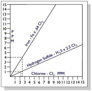 Example in dotted lines: 4 PPM Fe requires 2.6 PPM of Cl2. 1 PPM H2S requires 2.2 PPM of Cl2. Total Cl2 required is 2.6 + 2.2 = 4.8 PPM Cl2. can be calculated. Example: 20 PPM H2S x 2.2 Cl2 = 44 PPM of Cl2. 20 PPM Fe x .64 Cl2 = 12.8 PPM of Cl2 iron or sulfide is 2 P.P.M. or more. |
|
If using a 42 gallon pressure tank, the No. 2 hole on the chemical feeder should be used. This will dispense about 8PPM of Cl2, and a filter with 1 cube of activated carbon after the unit will eliminate the excess Cl2. If using the chemical feeder for iron removal or extremely high H2S, it is necessary to use a retention tank and a back washing valve on the carbon filter. The Chemical Feeder will hold about 4 lbs. of Cl2 (1 gram tablets). If it is adjusted to the No. 1 hole, and using a 42 gallon pressure tank with 1 cube of activated carbon, the system should process approximately 20,000 gallons of water before the unit would need refilling. |